|
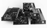
MD 288Elite Plug-In Modules
Ultra High Density Dimmers Designed to Pack a Lot of Power
Advanced Power and Control Pin Design
Applying this advanced technology insures solid electrical contact for extended, continuous service.
Custom Control by Mixing and Matching Modules
Take a look at our menu of dimmer modules, all of which are designed to meet your demanding lighting needs. |
Standard Dimmer Modules
Deluxe Dimmer Modules
Non-Dim Modules
Air Current Modules
High Rise-Time Dimmer Modules
High Rise-Time Deluxe DimmerModules
*Modules with control signal LED, non-dim select switch and control override pushbutton
|
|
ARCHITECTURAL & ENGINEERING SPECIFICATIONS MD 288Elite Plug-In Modules |
|
The power devices shall be mounted on a beryllium oxide substrate for maximum heat dissipation. The substrate shall be encapsulated in an epoxy-filled, high impact plastic case, with an opto-isolator, trigger and snubber network. There shall be 2500 volts of isolation between the AC line and the control signals in the SSR assembly.
The module shall be assembled on an extruded aluminum chassis at least 0.200" thick. The chassis shall form the basic heat sink for the module and provide for both air entry into, and flow control through the module. This heat sink shall be adequate to maintain a safe operating temperature for all components within the dimmer rack, with all dimmer and air current modules properly installed.
Each module shall be provided with a non-conductive Lexan-type cover to prevent accidental user contact with line-voltage energized components. Systems allowing contact with line-voltage level components on the module shall not be acceptable.
Each dimmer module shall have an integral inductive toroidal filter (one per discrete dimmer channel) mounted within the plug-in chassis. The design of the filter shall reduce the rate of current rise resulting from SSR switching. The end result of this filter will in effect:
The module shall be designed to operate on 100 to 140 volt AC lines at either 50 or 60 hertz. Each dimmer module, in conjunction with circuitry in the dimmer rack, shall maintain the approximate output RMS voltage to the load with respect to momentary fluctuations in the AC line. The dimmer shall maintain these standards with loads ranging from 100 watts up to the moduleŐs full rated capacity.
The power efficiency of the dimmer shall exceed 95% at full load. Switch-on verses switch-off response times shall be within 1/60 of a second for all loads.
There shall be less than 0.1 volt DC component on the dimmer output. Dimmer output shall be symmetrical at all times.
The faceplate of Deluxe modules, when specified, shall include an LED indicator for each channel which shall track the relative control signal to the module. It shall also include a pushbutton which when pressed, shall cause the channel to go to full output voltage.
Deluxe dimmer modules shall also provide an internal switch for each channel to allow the user to select whether a channel shall operate as a dimmer or as a non-dim. This function shall allow any dimmer channel in the system controlled by a Deluxe dimmer module to serve as a non-dim. Systems requiring the user to exchange dedicated non-dim modules for dimmer modules in the field to achieve a non-dim function shall not be acceptable.
Constant modules, when specified, shall conform mechanically to the specifications of a dimmer module. However, it shall contain only a thermal magnetic circuit breaker of the appropriate rated, mounted on the faceplate of the module. The breaker shall be UL listed as a primary branch circuit protector, and shall be switch rated.
To maintain the integrity of the rack's cooling system, Air Current modules shall be required to fill unused, prewired, module slots. The faceplate of the module shall be finished to match that of the other modules in the system. The length of the Air Current module shall be approximately half that of a dimmer module.
Dedicated Non-Dim modules, when specified, shall be completely solid-state. All dedicated Non-Dim modules shall use solid-state relays as their power device. The SSR shall solely control and carry the full load of the circuit.
A dedicated Test Module shall be available providing the following LED displays on the test module face:
The modules specified herein shall be the MD 288Elite series as manufactured by Teatronics Lighting Controls, Inc.
Deluxe Dimmer Modules
MD 288E 412D -- Quad 1.2kw*
MD 288E 224D -- Dual 2.4kw*
MD 288E 160D -- Single 6.0kw*
MD 288E 1120D -- Single 12.0kw*/**
Non-Dim Modules
MD 288E 412N -- Quad 1.2kw
MD 288E 224N -- Dual 2.4kw
MD 288E 160N -- Single 6.0kw
MD 288E 1120N -- Single 12.0kw**
Constant Modules
MD 288E 224C -- Dual 2.4kw
MD 288E 160C -- Single 6.0kw
MD 288E 1120C -- Single 12.0kw**
Air Current Modules
MD 288E 100 Fill unused, prewired dimmer module locations
MD 288E 200 Fill unused, prewired 12kw dimmer module locations
High Rise-Time Dimmer Modules
MD 288E 8224 -- Dual 2.4kw
MD 288E 8160 -- Single 6.0kw
High Rise-Time Deluxe Dimmer Modules
MD 288E 8224D -- Dual 2.4kw
MD 288E 8160D -- Single 6.0kw
Control Module
MD 288E CM -- Control Module
Test Module
MD 288E-TM -- Universal Test Module