 EM-ONE Electronics Module
Main Power Disconnect (48-slot rack only)
Custom Power Requirements
Custom Control Requirements
EM-ONE Electronics Module
Main Power Disconnect (48-slot rack only)
Custom Power Requirements
Custom Control Requirements
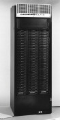 MD 288Elite
High Density with Maximum Flexibility
The versatile MD 288Elite Modular Dimmer Rack is designed for flexible dimmer configurations in a compact space. The Teatronics Lighting Controls high density MD 288E 7200 dimmer rack can accommodate up to 288 1.2 kw, 144 2.4 kw, 72 6.0 kw, 36 12.0 kw dimmers, or any configuration of dimmer modules as specified. The MD 288Elite is also available in a 48 module configuration as the MD 288E 4800.
Solid Construction / Efficient Cooling
All control and dimming modules are the plug-in type. The modular design construction allows ease of module relocation. The dimmer modules are fabricated with a proprietary aluminum extrusion die. This insures efficient cooling, excellent performance, and extended life of the electrical components. Our rugged mechanical design and sturdy construction results in safe and dependable connections for power and control.
Each dimmer module is cooled individually with fresh air through the front of the rack. All modules cool evenly with warmed air exhausted through the top of the rack. Temperature sensors and fan-speed control electronics are employed to maintain a safe operating temperature range. In addition the MD 288Elite protects itself with automatic dimmer shut-off, should the internal temperature rise above safe operating limits, and restarts itself when a safe operating temperature is restored.
Simple Electrical Installation
The MD 288Elite Rack requires front access only for installation and maintenance, enabling it to fit easily in equipment rooms with space limitations. This rack can be driven with AMX-192 or DMX-512 protocol. It also accomodates an EM-ONE control electronics module (optional). In addition, analog control is available for up to 36 dimmers per rack, 12 per phase.
You can expect long-term, reliable operation thanks to the advanced power and control connection technology. The MD 288Elite Modular Dimming Rack, combined with the MD288Elite Modules, will provide you years of trouble-free operation ..... an Elite combination that won't leave you in the dark!
| UL® LISTED92j1 |
Each section shall be substantially framed with code-gauge formed steel and extruded aluminum structural members and completely enclosed with code-gauge steel and/or aluminum panels. All exterior surfaces shall be properly primed and finished. Each rack section shall have a hinged, locking front door, with a grill to allow air intake across the face of all dimmer modules.
The construction of the entire assembly shall require only front access for installation and routine maintenance. All line, load, and control wiring shall enter through removable conduit access panels in the top and bottom of the cabinet. Access to the interior of the cabinet for installation and service shall be from the front, requiring removal of plug-in modules as needed.
Each 72-slot rack section shall accommodate up to 72 dimmer modules. Each 48-slot rack section shall accommodate up to 48 dimmer modules. Three multi-protocol control modules, one per rack section/phase, plus one spare per Dimmer Bay, shall be provided for all systems. Any combination of single 12.0 kw, single 6.0 kw, dual 2.4 kw, or quad 1.2 kw modules may be utilized in the rack. No module shall power more than 100 amps and systems employing quad 2.4 kw dimmers shall not be acceptable. The predetermined number of wired spaces for MD 288 ELITE series modules shall be provided as scheduled herein, or on drawings. Additional prewired module spaces shall be provided with plug-in air flow control modules to allow future dimming system expansion. Unused module spaces shall be provided with blank cover plates to maintain proper system cooling.
Each module position shall contain module support rails and control pin configurations to accept the module specified. Power pin connectors shall be made of solid brass for reliability and designed to maintain a spring contact.
The control module positions shall contain gold-flashed printed circuit card connectors configured to accept the plug-in control modules.
The cooling of each rack section shall be via forced-air, with an internal, variable speed high volume fan. Each rack shall draw in cool air from the front of each cabinet and exhaust warmed air at the front top of each cabinet. Systems not drawing in cool air from the front of each module shall not be acceptable. The cooling system shall maintain an appropriate operating temperature with respect to the needs of the active power handling components of the system, in an overall environment not to exceed an ambient temperature of 40 degrees Centigrade (104 degrees F). Temperature regulation shall be accomplished by the variation of the intake air volume drawn over each module, incorporating temperature sensors and fan-speed control electronics. The fan shall start and stop automatically on demand by sensing the presence or absence of a control signal.
Each rack shall be provided with an automatic air-temperature sensor to shut off all dimmers in a rack should the internal temperature rise above safe maximum operating limits. In an overheat condition, the fan shall continue operating. When a safe operating temperature is restored, the system shall automatically reset allowing normal user control.
Overtemperature conditions shall be prevented by the use of high-magnetic thermal circuit breakers in the dimmer modules. The dimmer primary circuit shall have a thermal element rated to trip and open the circuit breaker at a temperature greater than 40 degrees Centigrade (104 degrees F). The dimmer rack shall have an overtemperature circuit which sends a signal to the system control console overtemperature indicator (if provided) and to the overtemperature LED provided on the control modules in the rack. The overtemperature device shall be set to sense and send a warning signal at temperatures 10% above the control temperature, which is approximately 35 degrees Centigrade (95 degrees F).
The finished dimmer rack assembly shall operate on 120/208 volt, three phase, four wire plus ground, electrical service, with the internal power buss structure sized for the specified current capacity, (not to exceed 800 Amps per phase). All power and signal connections within the rack shall be factory wired to screw termination points, neatly dressed and labeled. Each rack section shall be designed for bottom power feed entry. Each rack section shall have a removable panel on each side for pass-through and/or power feed entry.
The manufacturer shall provide adequate space for installation of all necessary field wiring as per National Electrical Code (NEC) standards. Other than the wiring lugs provided for the installing contractor, all internal wiring shall be factory dressed, labeled, checked, and tested.
Where required, there shall be available from the manufacturer, auxiliary cabinets or power bays to house such auxiliary items and equipment as Main Disconnect, System Branch Breakers, Relay Systems, etc., to achieve the specified operation of the lighting control system.
The control modules shall be no larger than 2" high x 8.25" wide x 13" deep and shall weigh no more than 3.0 lbs. All circuit cards shall be 0.062" (minimum) thick, solder-plated, through-hole plated, glass epoxy.
Appearing through, but not attached to the face plate of the control module, shall be the following three information indicators:
| Designation: | Color: | Purpose: |
| Signal | Green | Indicates presence of control signal. |
| Power | Amber | Indicates presence of AC power input |
| Over-Temp | Red | Indicates overheat condition. |
Identification of each indicator shall be via a permanently screened legend.
All control modules shall be completely interchangeable with all other control modules in the system. Connection of the control module to the dimmer rack shall be via one HDI type connector. Systems that do not employ front removable plug-in control electronics, or systems that require tools to remove control electronics, or systems that use multiple control connectors, shall not be acceptable.
The control input signal to the system shall be user-selectable between either USITT AMX 192 or DMX 512. Selection of the type of control signal input shall be via user-accessible switches on the control module. A maximum of 36 analog control signals (0-10 vdc), 12 per phase, may address the dimmers. The analog signal may be either discrete or pile-on in relation to the multiplex control protocol.
Dimmer modules shall be fed following a standard phase rotation, i.e. Module 1 - Phase A; Module 2 - Phase B; and so forth. No more than four consecutively numbered dimmers shall be on the same phase. Consecutively numbered dimmers shall be located in sequence in the dimmer rack. Where fault current protection is required, fuses may be installed at the electrical service input to the rack's power buss structure. Systems not capable of fusing the power input shall not be acceptable.
The finished dimmer rack shall be completely factory tested. Each dimmer rack shall include two spaces for the storage of any spare control and/or dimmer modules. The entire dimmer rack shall be UL recognized and labeled as a dead front switchboard with a rating of 10,000 AIC.
An MD 288E TM, Dimmer Test Module, shall be provided with each rack system.
The dimmer rack specified herein shall be the MD 288Elite series as manufactured by Teatronics Lighting Controls, Inc.
The following shall be available as options to the MD 288Elite Dimmer Rack:
EM-ONE Electronics Module
Main Power Disconnect (48-slot rack only)
Custom Power Requirements
Custom Control Requirements